A guide to improving your car’s downforce and aerodynamic performance efficiently, without wind tunnel testing or CFD analysis.
Improving downforce can seem like a big challenge when you don’t have the tools to measure increases in performance. How do we know if the wing we put on our car or the air dam we spent a weekend making help at all? The tools of the aerodynamic trade can be out of reach for mere mortals. Renting a wind tunnel is cost prohibitive for many large-scale race teams, let alone a few friends looking to have fun at the track. Computational Fluid Dynamics (CFD for short) is a great tool that brings aerodynamic testing right to your desktop computer but the software isn’t inexpensive and a lot of training and experience is required to be able to get useful information from it.
I’m here to tell you that dramatically improving the downforce and aerodynamic efficiency of your race vehicle is much more accessible than you think. Certainly, a wind tunnel and CFD can take you to the next level, but right now, a lot of speed is left on the table due to misinformation, misunderstanding and a fear of making your vehicle perform worse.

First things first, this guide applies to production-based cars. At Professional Awesome Racing, we specialize in time attack and time trial racing. This guide can be helpful for touring car racing, endurance racing, club racing and more, but is not intended for open-wheel formula cars.
We see people saying that trying to improve downforce for lower power cars is a waste of time because the cars don’t have the horsepower to make up for the added drag. There may be instances where this may be true, but we have seen this isn’t often the case. We’ve worked with 90 hp Mazda Miatas and 1000 hp Mitsubishi Evolutions. The information applies for both. You can make downforce without adding much drag, and in some cases, even reducing drag!
Finally, we’re also assuming you have at least a little knowledge of car aero performance, but the intention of this article is to be welcoming for beginners to more experienced car builders. Enough with the intro, let’s get down to business.
Front Aero
We’re going to start at the front of the car and work our way to back. I know when I first started getting into upgrading aero, getting the front to perform was always my biggest fear. At the back of the car, you could slap on a wing and make it as big as your wallet allowed. But how do you get more performance out of the front? Well, after years of reading, testing and research, my mindset has flipped. Downforce at the front of a car is relatively easy! Why? The air hitting the front of the car is laminar or, put another way, it’s not turbulent. The rear of the car is dealing with all sorts of vortices, boundary layer effects and issues that you really need CFD or a wind tunnel to study. Without having those issues to deal with, designing for the front is much easier.
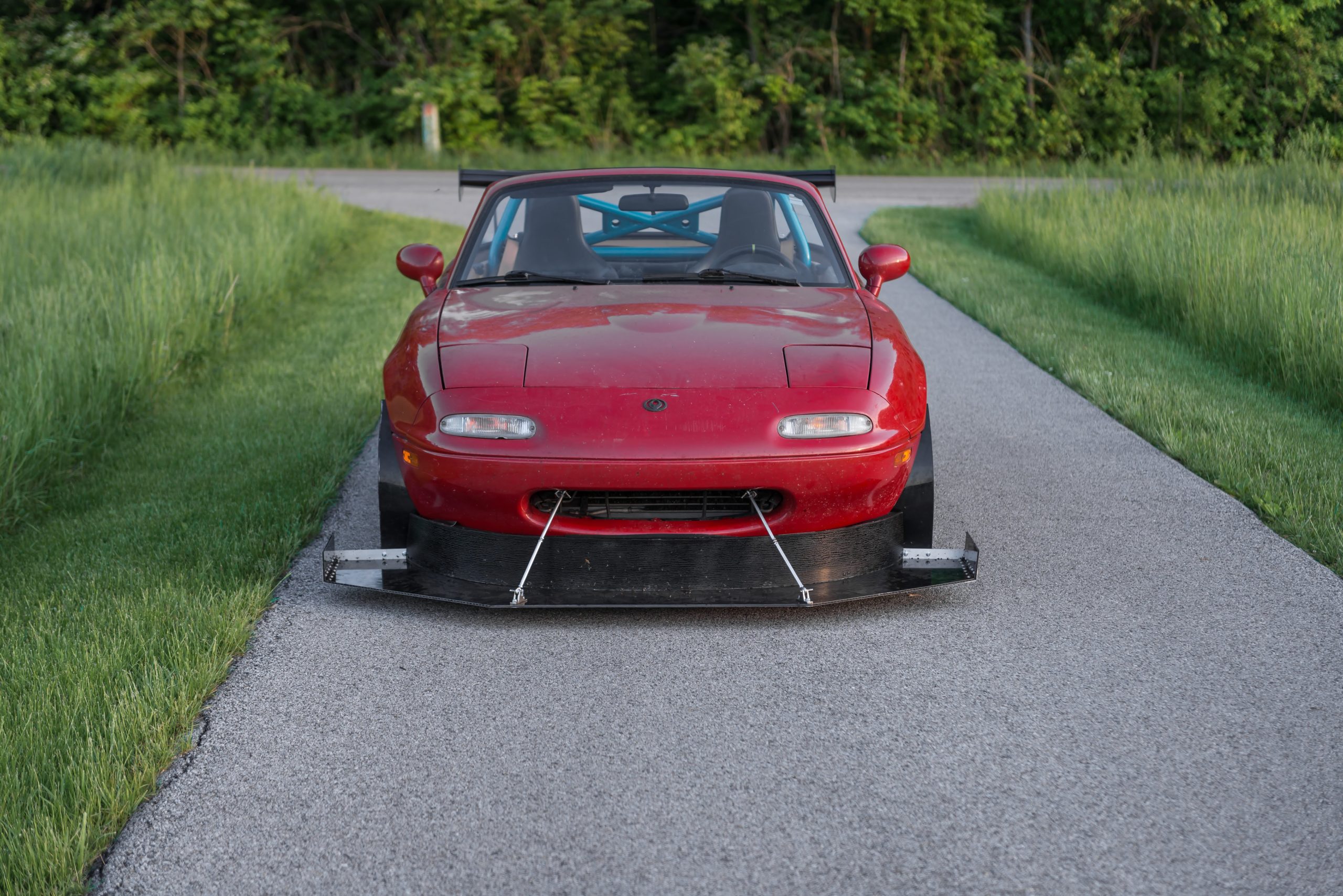
Splitters and Air Dams
So where to start first? Since we’re dealing with production-based cars, let’s talk splitters and air dams. The splitter is a common, effective, and very efficient way to make a healthy amount of downforce. It splits air hitting the front of the car. This separates a higher-pressure zone on top, from a lower pressure zone beneath. What do you get when you combine those two zones? Downforce!


Most splitter applications are vehicle specific AND race series specific. This means, it’s hard to find an off the shelf solution. Because of this, many racers construct their own. The first place to start is on the splitter material itself. The material should be stiff, lightweight, easy to work with, impact resistant and not too expensive. The last point being important as splitters can take a lot of abuse being so close to the ground. Common material choices are plastics, plywood, sign board materials, carbon fiber honeycomb composites, Kevlar composites and aluminum. Each material has its pros and cons. We use Alumalite sign board material and plywood for many of our splitter designs. Both offer a good balance of strength and weight to cost. For more detailed information on splitter material choices, check out our YouTube series. We cover the positives and negatives on each choice thoroughly.

Once you have made your choice on what material to use, a critical aspect of your splitter system is mounting it to the vehicle. It’s easy for your splitter, if well designed, to see 500+ pounds of force trying to pull it off the vehicle. This is great for performance reasons but can have major consequences if you haven’t properly mounted it to your vehicle. We’ve seen a lot of people mounting their splitter directly to a factory plastic bumper. These designs fail as the plastic isn’t strong enough to hold it in place.
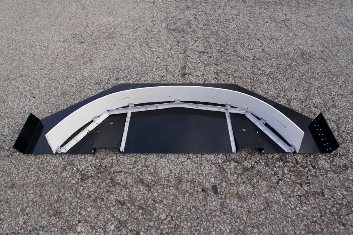
Ideally your splitter should have an aluminum or steel frame that distributes the downforce loads over a wide area. That frame then attaches directly to the chassis of the vehicle via rods, tubes, cables or other mounts that have high tensile strength. I cannot stress this point enough. We’ve seen a lot of splitter failures recently, as designs get more aggressive. We foresee a major injury occurring when a splitter rips off and all the front-end downforce disappears. Please be careful!

Now that you have your splitter material and know how to attach it to the vehicle, what next? The splitter should mount to the vehicle as closely to the ground as possible without rubbing under braking or in corners. This is easier said than done, but critically important. Splitters’ downforce performance improves dramatically with reduced ground clearances. The problem is, if you fully seal it to the ground, not only do you wear or damage your splitter quickly, you can also greatly reduce downforce due to the airflow beneath it being cut off. This can be very dangerous.
Suspension and Splitter Interaction
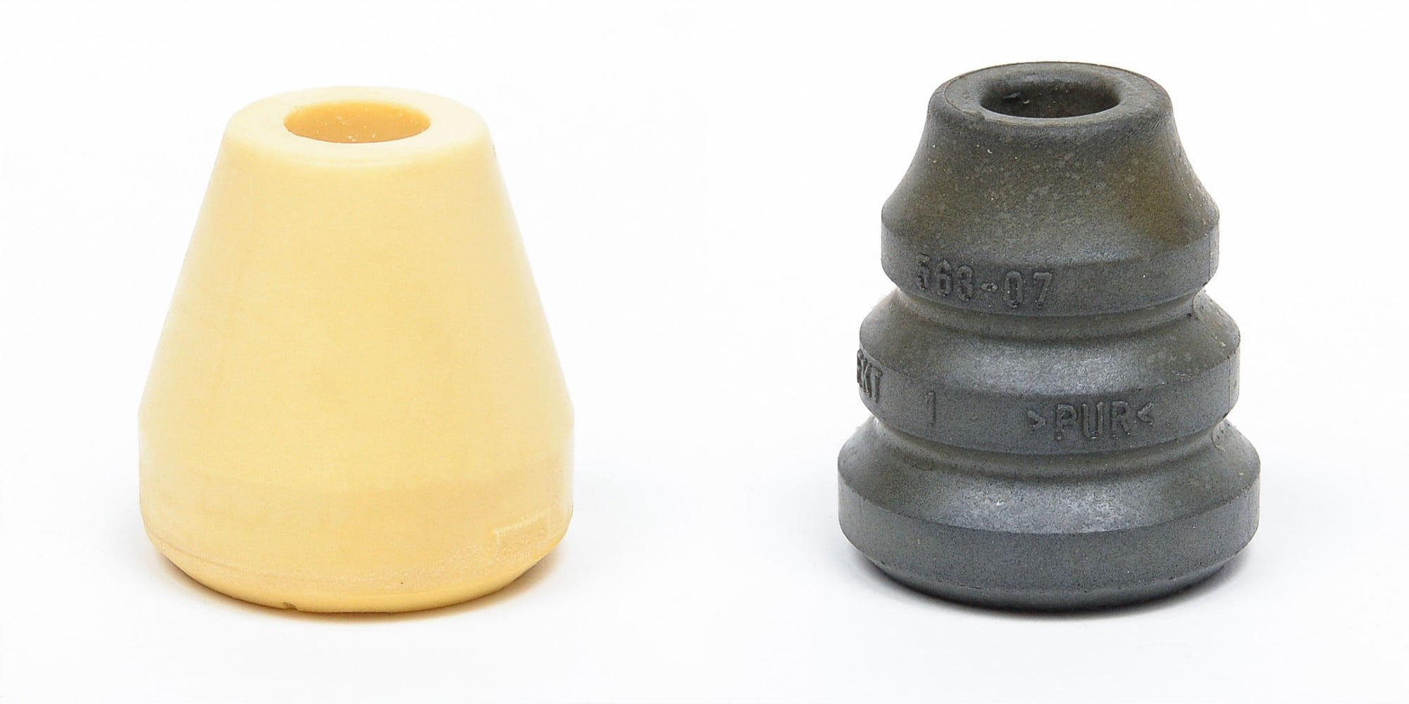
This leads me into the importance of having a well-designed suspension setup that can keep the aerodynamic pieces under control. The more stable you can keep your splitter in relation to the ground, the more consistent your splitter’s aerodynamic performance will be. With that said, if you stiffen the suspension to provide a stable aero platform, you can reach a point where you start sacrificing mechanical grip. This can hurt cornering performance. Finding a balance is key and will require testing for your specific vehicle. Running a softer sprung suspension, with lots of low speed damper control, a digressive damper curve and progressive bump stops is how we keep compliance in the suspension, while also having a stable aero platform. But again, testing is key to finding the right setup for your vehicle.
Splitter Angle
With the splitter mounted low, but not too low, another overlooked aspect is splitter angle. Now this can require testing to find the right balance as well, but in general, if the rear of the splitter is at a slightly upwards angle, you can see a gain in downforce with minimal increase in drag. Angles should be in the .5 to 2 degree range but testing here can yield better results. While driving in a safe area, use string tufts to see what angles and speeds show strong airflow attachment. This can allow you to adjust the angle of attack for maximum performance. Higher angles will create more downforce, provided you have proper air attachment. Keep in mind, test at the speeds you’re expect to corner at. Always optimize your splitter and car for your expected use.
Splitter Air Dam

Next, we will discuss an often overlooked and a critical piece of your splitter system, the air dam. The air dam is the vertical part of your splitter that attaches perpendicularly to your main splitter plane and parallel to your bumper. We see many splitters that do not feature this part. If you’re one of the offending people, you’re really hurting your performance.
The air dam’s primary goal is to efficiently create a high-pressure zone on the area of your splitter that’s exposed in front of your bumper. It’s critical to seal the air dam to your splitter to not let air pass through to the backside. What we see are gaps left in this area, allowing air to bleed above the splitter and below the bumper. This hurts the high-pressure zone, increases drag by not efficiently moving air around and over the vehicle, and hampers cooling performance by not forcing air towards intercoolers, air filters, oil coolers and radiators (and potentially allowing the air to get to the backsides of these cooling systems, hurting performance even more!). Your air dam should seal tightly to your splitter and bumper to control the air as much as possible.
Splitter Extension
Splitter extension, forward of the front bumper, is another important aspect you should take into consideration. The rule here is, the longer the better… as long as you aren’t smashing it into the ground under braking and cornering. Additionally, your splitter length should not compromise the height at which it can run. Realistically, this works out to be about 4” – 8” of extension in most cases. It should be noted, that the longer you extend, the downforce reward diminishes. The high-pressure area created by the air dam and front bumper can only be so large. Try and make it as long as physically possible or within what your racing class’ rules allow.
Splitter End Fence

Splitter end fences are one area of splitter design that are really car dependent. With that in mind, CFD and wind tunnel testing are important to maximize their designs. Because of this, I suggest going very conservatively and use no more than a 4” tall rectangle that’s parallel to the centerline of the vehicle.
Splitter Diffusers


Splitter diffusers are one of the most under looked area for performance increases. Because of this, they have one of the best upsides for untapped aero potential. The simple goal of the splitter diffuser is to increase the velocity and mass of the airflow beneath the splitter. More air flowing at faster speeds means an increased low-pressure zone beneath the vehicle. The lower the pressure, the more you will gain downforce. The added benefit is the possibility of moving air away from potential high-pressure zones, such as where the tire meets the road. This reduces additional drag and lift. Win-win!
We sell splitter diffusers of a few different shapes and sizes that are optimized in CFD to work in many applications. You can design your own as well but take care to ensure proper attachment of airflow to the diffuser curve. Being overly aggressive can cause airflow separation, reducing downforce and increasing drag.

A few final splitter tips, tricks, and ideas. If you can design a mounting solution that allows for adjustment of height and pitch separately from adjusting your vehicle’s ride height, you can dial in the aero and suspension for the track separately.
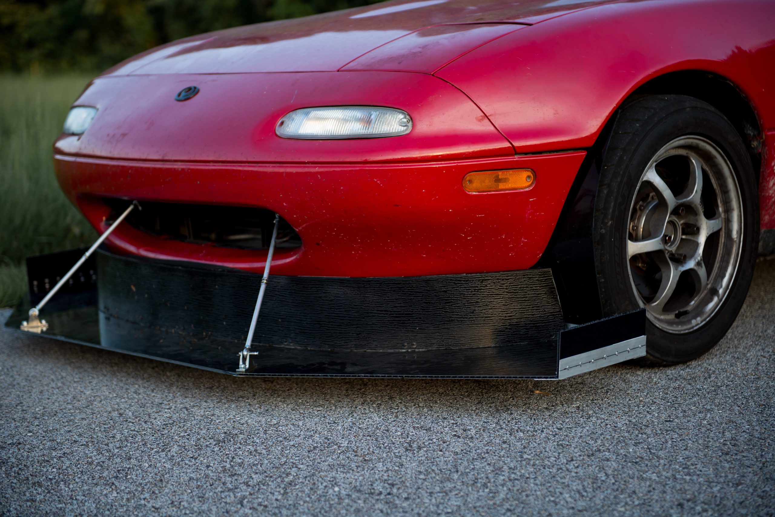
Always take care to securely attach the splitter. Consider using cables or our flexible splitter support rods for the front mounting positions. The reason being is that the splitter is most likely to hit the ground in this area. Using solid rods can damage the rods, your mounts or the chassis of the vehicle. Cables and flexible rods will move, saving your car from damage. The downside of cables is that they cause more drag than you’d expect considering their size. Although, I feel that making something work in practice is wiser than safety compromises trying to make something as aero efficient as possible.
Front Bumper
We spent quite a lot of time on the splitter, because of how important they are to an efficient aero package, but let’s work our way back just a touch. The front bumper is the next area where we see lots of room for improvement. First, get rid of any unnecessary openings. For styling purposes, we see a lot of ducts and vents that go nowhere. Seal these up with a little sheet metal and a few rivets. This reduces drag and helps increase downforce.
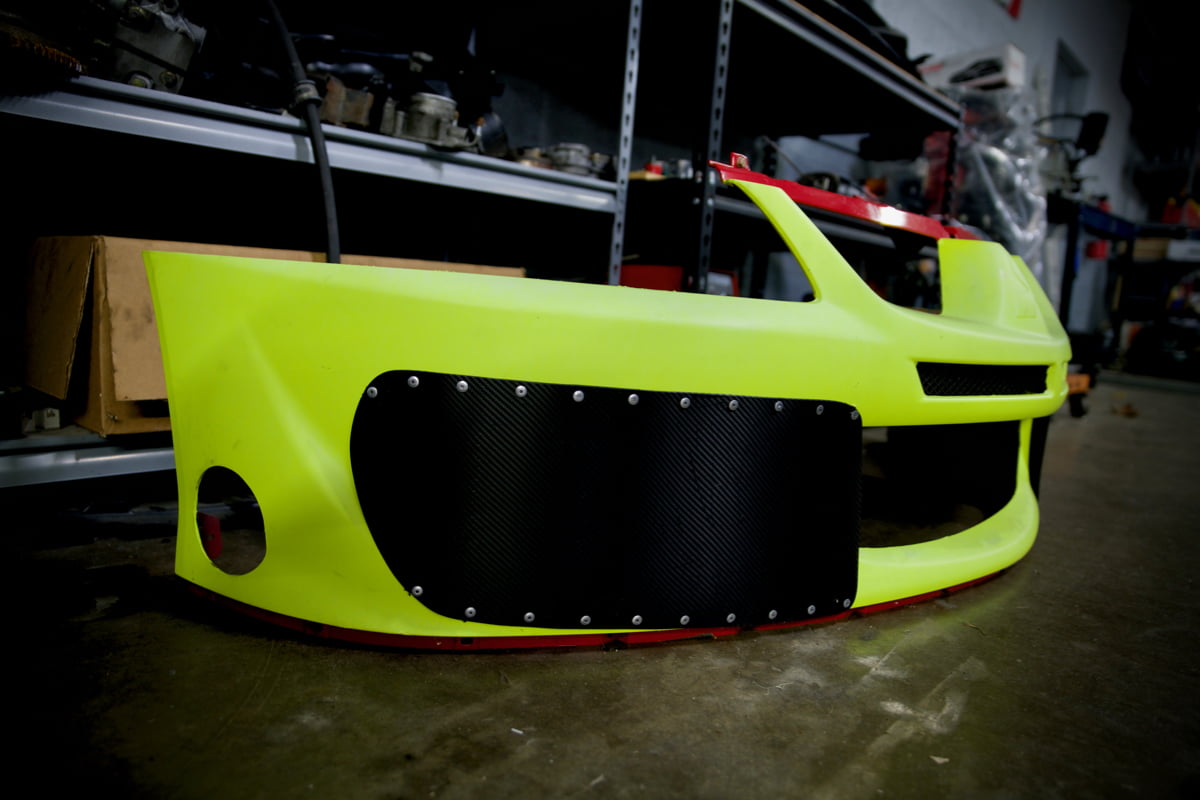


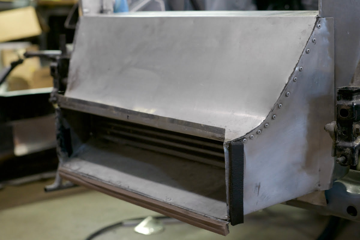
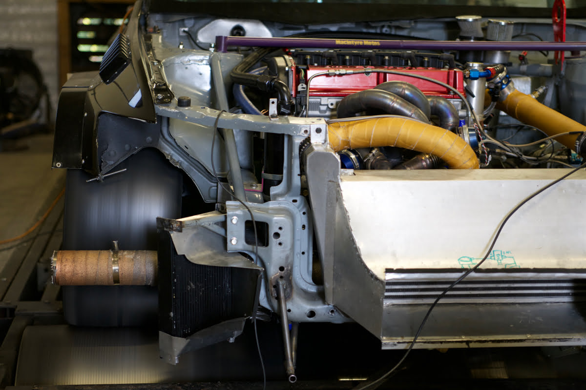
Speaking of unneeded openings in the bumper. Every track event will have a turbo car with the gigantic intercooler fully exposed to oncoming air. It may look cool, but not only is it causing unneeded drag and a reduction in downforce, it can hurt the cooling performance of the car as well. This is where ducting comes in handy. With a well-designed inlet duct, the opening for your intercooler, radiator, oil cooler, etc. should be about 1/3 the surface area of the heat exchanger. If your intercooler core is 20” x 30” (600 square inches), the opening to you duct should be about 200 square inches. The opening should then smoothly transition to the full area of the intercooler, radiator, oil cooler, etc.
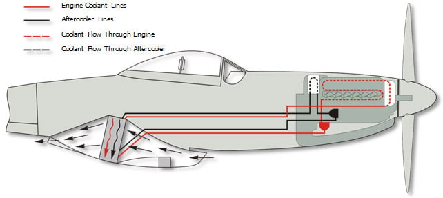
We adopted this technique from the cooling systems of WW2 fighter planes. They used the design to efficiently extract heat from their massive engines without causing unnecessary drag. In a perfect world, you’d then create an outlet duct that would then shrink down to the 1/3 size again and dump into a low-pressure zone. Figuring out well-defined low-pressure zones on a car is tough though. If you go this route, be certain you test very carefully to ensure proper airflow out of the duct. This is a prime example of why doing the front aero is easier than the rear. It’s easy to find the high-pressure area of the front bumper, but the low-pressure zone following the car is only easy to find directly behind the vehicle.


Cooling is another topic I want to touch on briefly. Any cooling inlets on your car will increase drag and can reduce downforce, but obviously you can’t get rid of them. What do you do? Size your systems accordingly. For time attack/time trial vehicles, measure oil, air inlet, coolant, and brake temperatures to learn trends. On our racecar, we found that we were over cooling the oil and did not need a full-sized cooler for the 2 or 3 laps we’d run at a time. This allowed us to seal up the oil cooler ducting, which improved aero performance. Finally, we removed the cooler completely. This reduced the chance for leaks from the extra lines, as well as saved weight.
You can check brake rotor temperatures via brake paint as well as infrared (IR) temperature sensors. With this knowledge, it might turn out that you don’t need the brake cooling ducts in your bumper. With temperature data you can also better set brake balance and make pad choices, but that’s a whole other article! Endurance racers, the same applies for you, but in reverse. Long story short, watch your temperatures and adjust cooling capacity accordingly!
Front Fenders and Hood
A significant difference between how a car works on the street and how it works on the track is heat management. Race cars produce a lot of heat, and airflow is an absolute requirement to keep temperatures in check and parts from breaking. This is where the hood and front fender area are critically important. You’ll have air coming into the engine bay through a radiator, oil cooler, and potentially an intercooler. This air needs a place to go.
Hood venting is how you allow the air to escape efficiently. The problem is that your hood sees a variety of pressure zones. As oncoming air moves up from the bumper and curves over the hood, you can see a velocity increase. This reduces air pressure and causes lift. Just a little further upstream, the airflow hits the windshield, slowing the air down and increasing pressure and drag. Finding a smooth flow of laminar air and adding venting, much like we sell here, will allow the under-hood air to vent efficiently. Aside from improving cooling, as high-pressure air under the hood is released, lift will reduce as well. This improves the downforce of the vehicle.


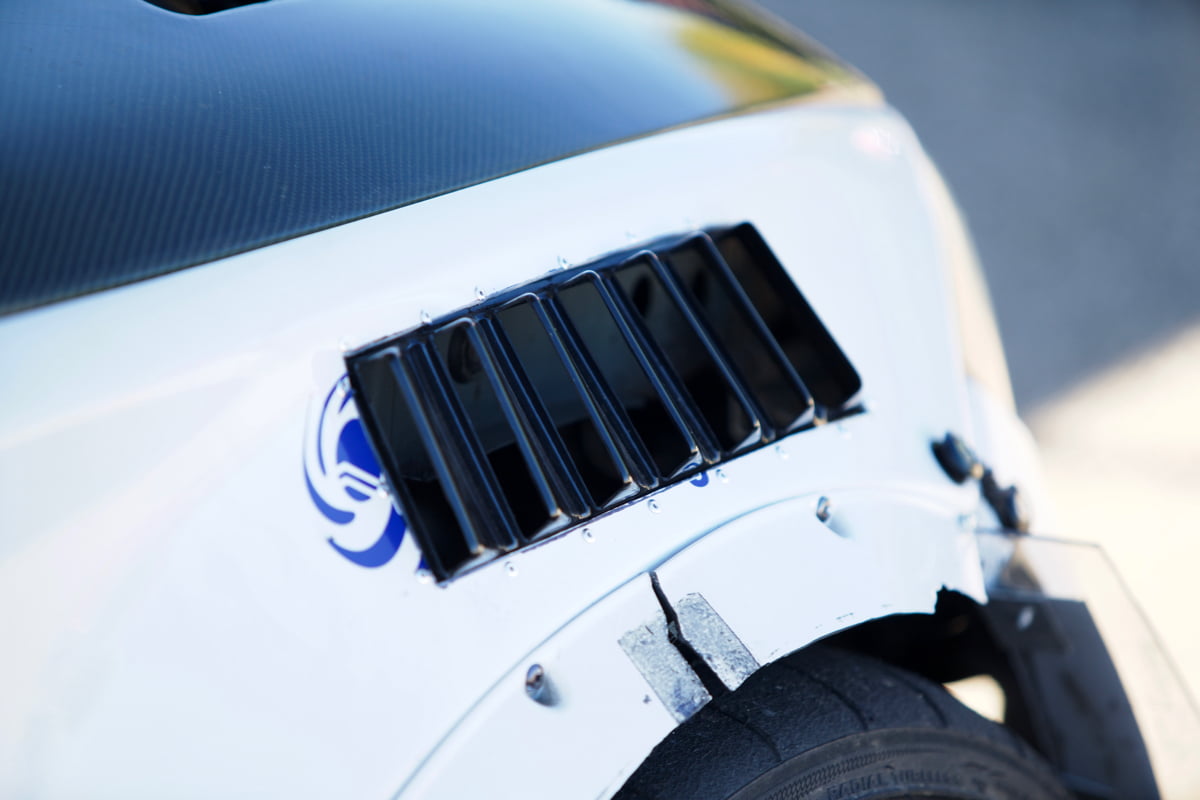

The same principles apply to the fenders. The rotating tire in the fender can cause a significant increase in air pressure, which pushes upwards on the fender. Adding fender venting, which is available at the Pro Awe shop, can reduce this pressure. This in turn improves downforce numbers. Fender venting is a widespread practice in prototype racing and well-designed vents can achieve large increases in downforce. Another benefit can be an increased amount of airflow around your brake system, reducing the need for added brake cooling. Additionally, all this venting can work together with your splitter diffuser system. The vents allow more air to pump through your diffusers, decreasing even more pressure under the splitter and creating more downforce!
Front Tire Deflectors/Side Spats
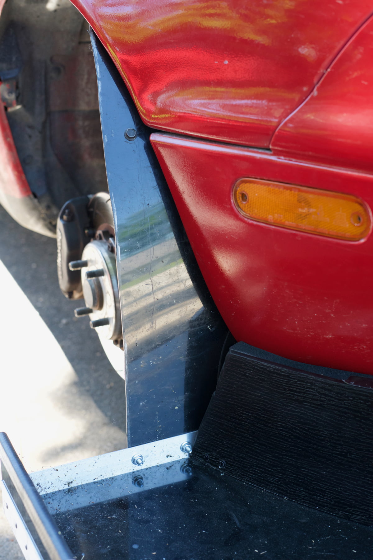

On many track cars, wider tires are shoved into the small factory fenders. The tires can then extend out beyond the sides of the vehicle when looked at from the front. Exposing tires in this manner will create drag and lift. Simple tire deflectors, also called side spats, can keep air from hitting the tire’s rotational air mess, improving your aero efficiency. If you do it right, turning them into a splitter support and/or a small air dam isn’t hard as well!
Canards

I will just touch on this topic briefly. It’s difficult to know how canards will affect the aero performance of any specific car without testing. Canards are commonly used for balance changes to vehicles in race series that have limited aero rules. I’ve seen cars where they are extremely efficient and critical for aero performance and other vehicles where they are completely inefficient and hurt overall performance. I’d investigate these only when adequate testing can take place, be it at the track, CFD or a wind tunnel.
Rear Wing
We were just on the front bumpers and suddenly, we’re jumping straight to the rear wing. What gives? Underbody aero, such as flat bottoms and diffusers are extremely complex and vehicle specific. We’ll touch on them later as testing is so critical to these parts.

A rear wing is a very efficient way to balance out the massive front aero you’ve added to the car after reading this article, but there are some considerations to keep in mind. First, work with companies that supply data for their wings. If you have followed our advice and made a nice, simple front splitter, you might make 300 pounds of front downforce at 80 mph. Alternatively, with a huge splitter and monster diffusers, all working properly, you might be up to 600 pounds of front downforce. You’ll need a rear wing to match accordingly. Having data is the only way to figure out the best wing for your needs.

Once you have that data, you need to know what percentage of downforce you want on the rear of your car. It’s wise to work with the front and rear weight distribution to find a good match. For example, a Miata has a weight distribution of 50% front / 50% rear. With this information, shoot for a 50% front / 50% rear aero balance. What about a 60% front / 40% rear Mitsu Evo? Here you’d go for a 60% front / 40% rear aero balance. I’d always recommend shifting that balance slightly towards the rear, so the car understeers under aero loads. It’s a little safer, easier to drive and more confidence inspiring.
Once you know how much rear downforce you want to make, look at the wing’s downforce vs. speed data. Most provided wing data is free stream tested, meaning, they aren’t the exact numbers you’ll see on your car.
Putting the same wing on the back of a slippery Toyota Prius will see different downforce and drag numbers compared to being mounted on a convertible Mazda Miata. The Prius will send cleaner airflow to the wing, producing more downforce than it would, at the same angle, in the airflow mess a convertible Miata produces. You’ll need to size your wing based on how the air flows towards the back of the car.
You can move you wing mounts up to get cleaner airflow above the car. Additionally, you can move the wing back to create move leverage acting upon the chassis. Just like the front splitter, rear wing mounts are critical for safety. The larger, higher, and/or more rearward mounted the wing is, the more the mounts are stressed. Go conservative here and make sure the wing doesn’t fail or you could quickly find yourself going backwards into a concrete wall.
Rear Spoiler

I’m a fan of rear spoilers for multiple reasons, but keep in mind that they aren’t massive downforce generators. Spoilers can balance out high speed oversteer, instilling more confidence while driving. Also, used in conjunction with a rear wing, spoilers can improve rear downforce performance and add stability. With a well-designed rear diffuser, a spoiler can also alter underbody downforce. Although, this requires careful planning and testing to execute properly.
Flat Bottom and Rear Diffuser
Here’s the thing, the underside of the car is a very tough aerodynamic nut to crack. You’ll have tire wake to deal with, which is way more intense than you can imagine. Moreover, the cool new front splitter you’ve designed will have major cascading effects behind it. Additionally, inflow from the sides of the car is a major challenge. Not to mention, a flat bottom needs to be properly sealed to the chassis above for the diffuser to work properly. Without the right flat bottom, the rear diffuser will not function as effectively, if at all.

I know some of you will insist on going this route without testing, so here are some tips. Starting the diffuser farther forward can yield positive results when trying to enhance the overall downforce of the vehicle. Just keep your aero balance in mind. The point the diffuser starts will be the point of lowest air pressure. This is where the car is being “pulled down” from and affects your balance.
Keep your angles conservative to reduce the chance of flow separation under the car, which will increase drag. I would say no more than 10 degrees as a starting point. Do string testing to ensure you have attachment of airflow to the roof of the diffuser. If you see attachment, you can try to push further. The center of the diffuser, when looking from the back of the car, is normally the area that works best. The outsides tend to struggle no matter what you do. Use vertical strakes to enhance attachment and keep area of healthy flow separate from areas of turbulence.
How to Test

String or wool tuft testing can be a terrific way to visualize airflow on the surface of your vehicle and ensure your components are working as expected. Some of the best ways to use strings are to check for flow on the surface of wings and diffusers. Grab yourself a GoPro and find a safe place to drive your vehicle. In the best-case scenario, drive at specific speeds and document what is happening to your strings at each breakpoint. 10-20 mph differences would be a good place to start. Test at speeds you’re likely to be cornering at. I’ll see huge downforce numbers regularly tossed about because aerodynamicists “test” at 160+ mph for big numbers. This doesn’t make sense if you have a car that corners at 60 mph.
If the strings are steadily flowing in the same direction, you have good surface attachment. If you see strings going all different directions, even pointing towards the front of the car, that is flow separation. You want to avoid situations like these on wing and diffuser surfaces in particular. Be careful to make sure the strings have enough room to move freely. If they touch one another or any sharp edges, they can get stuck and give you false information.

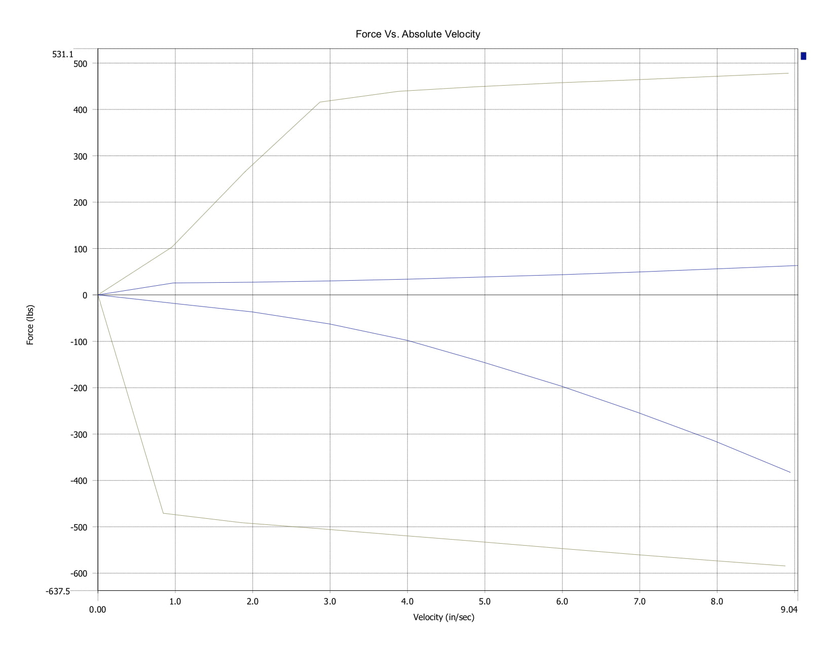
If you really want good data, find yourself a quality data acquisition system and datalog shock movement. Use the information to make calculations for downforce, aero balance, shock settings and much more. Going into how to use the data is outside the scope of this article. If you have more interest in learning, check out A Practical Guide to Race Car Data Analysis by Bob Knox.
Conclusions
Thanks for reading this far and hopefully we’ve given you some advice to push you in the right direction for your car’s aero performance.
We welcome questions! Feel free to comment below.
Want us to help you on your specific car? Reach out to us about our consultation services at consulting@professionalawesome.com.
Looking for parts you read about in the article? Head to Professional Awesome Aerodynamic Parts.
Tell us what you’d like to learn about next and we’ll try and help you learn from our experience. Thanks again!
How are you measuring/evaluating the changes? Increasing downforce will (normally) increase drag, without adding more HP to overcome the drag the decision needs to be made where best to use the available HP (straight line speed or downforce).
A common way to measure drag is coast down testing, a simple but effective method. However this also assumes that the car is able to be driven on the road. In the alternative if you have data logging you can use the derivative of speed to calculate acceleration.
A ‘crude’ way is to multiply the acceleration G force by 9.80665 to give acceleration in m/s². However this requires there to be almost no lateral G forces and the car to be at wide open throttle to remove as many variables as possible. However if you use the same part of the track then at least it is repeatable.
No matter what method, as speed increases acceleration will decrease due to the impact of drag. If the data shows that acceleration has improved then baring no other changes drag has decreased.
Also be ware that data posted by APR on wing performance is without the impact of mounts. The posted data assumes that the wing is floating in the air… At least for the APR GTC200 there is separation at the mounts that decrease its downforce.
For a street car, the easiest way to measure changes in drag is fuel economy and driving a lot of miles! I found on the Miata that a noticeable increase, 2-3 miles per gallon, in fuel economy that was repeatable. Obviously, there are other methods to test with, but we’re looking for big changes, although this method means we’re measuring without units. IE, I don’t know how much the CD on the car dropped, but it most certainly did, meaning I was headed in the right direction. Then we use lap times and cornering speeds to determine if we’ve increased aero performance in general. Is it super accurate and precise? No, but that’s not what I’m looking to achieve.
On our race car, we use shock pot data that is damped and we use data from the same track and measured at the same speeds in the same sections of track. With this method, we can have high precision on whether or not an improvement has been made in downforce, although, 500# of downforce at once track might be completely different than 500# at another track. Accurate? No. Precise? Yes.
Regarding the wing data, you’re absolutely correct and I reference that to some degree within the article. The data you see on the charts will not be exactly what you get behind the car, but it’s better than nothing!
This is an incredible write-up. Thank you.
Wow! This is great! Do you think adding a front lip spoiler (think Ezlip) would have any effect or is it just not big enough?
The front lips you see on eBay can make a little difference in reducing drag and maybeeeee reducing lift, but the effects will be minimal. If you can stick it on with double-sided sticky tape and it doesn’t fall off, then you know the forces it’s seeing aren’t that great, but anything to keep airflow from going under the car will help in some way (unless you have tunnels are a rear diffuser, but that’s a whole other story).
This is a great article, thank you for sharing. Is it possible to utilize the venturi effect and install ground effect to generate negative pressure(similar to old school F1 cars) on a street car?
It’s totally possible, but there a few considerations to take in mind.
1)Body control- The car’s body has to be very stable for safely and consistently creating underbody downforce.
2)Flow disruption- The car has to have a consistent flow of air to make this work, but items like wheel wake and inflow from the side skirt area can both help and hurt flow.
3)Testing- With the first two points in mind, you really have to test effectively to make a system work. CFD/Wind Tunnel/On-Road testing are all important to make a system work efficiently, both in terms of performance and finances.
Very well written and encompasses a large part of race car aerodynamics in very clear and visiual way! I have always wondered about the negative pressure area behind the car (in the wake right at the body) and i have seen some time attack cars use a tunnel from under the car routed inside the body and exits in the negative pressure zone at the back of the car. Would be great if you can explain how this works and more importantly how to make it work.
Diffusers/tunnels at the rear of the car make perfect sense to utilize the low pressure behind the car, to create a suction effect under the car and it’s even better with a rear wing that can help create even more suction. The issue is, it’s beyond the scope of this article to help design a good system, because the further downstream you are on the car, the more the effects of wheel wash, boundary layer and dispersed flow creates problems with proper attachment. Testing, CFD and/or wind tunnel all have to work together to design a really solid rear diffuser system. Hopefully, we’ll get to dive into that in a further article, but for now, we just don’t have a great explanation to provide.
Enjoyed the article gives a lot to think about
Confused by your claim that the Allard J2X was “one of the highest downforce cars in history” until I discovered you were talking about the little-known one-off 1990’s J2X-C, not the 1952 J2X model.
My apologies, I need to update the name!
We’re building a 300ZX and fabricating the front splitter. Lots of points here that we will apply to our design. PS-can you comment on the eBay wings? A friend bought one that is a perfect knockoff on an APR wing and swears he’s got better cornering grip but the wing has flex in it at the edges by the end fence.
Thanks!
BP
While I am not a fan of knock-off parts, if the profile is the same, it will work the same. That being said, if the edges are flexing, that’s scary. Aerodynamic failures should not be taken lightly. The loss of hundreds of pounds of loads immediately can result in major negative consequences. I’ve see cars totaled due to wing failure and injury, or worse, isn’t off the table in situations like that.
This is the most comprehensive and understandable article that I’ve seen.
My BMW 330 e46 race car has a splitter and a rear wing and I’m now looking at a rear diffuser. This article will help me with my choice of available products.
Ps the section on airdams has prompted me to relook at the size of the holes in my air dam which are for brake cooling. Perhaps they are too big?
Thank you very much for the kind words. In regards to the airdam comment. I am rethinking my ideas on brake cooling in how it relates to tire temperatures. My fear is going too small with cooling will increase brake and tire temps and negatively impact mechanical grip. I’ll be testing these theories next year!
Pretty much nothing relating to design/construction of rear diffuser.
It’s because a rear diffuser is extremely difficult to get right without access to proper CFD or wind tunnel testing.
I am installing an air dam on my e36 despite other competitors in previous seasons trying and ultimately removing them. You mention side skirts and under trays are tricky, I had planned on lowering the side skirts to the same height as the air dam. Seemed logical to me to seal off everything but the rear. Is this not a good idea? Would it be a better idea if I let air out of the engine and fender areas? Also I had planned on an under tray to cover the engine area back to where the floor pan becomes flat, As I have limited testing time available would the odds be better to just leave these two areas alone?
Thanks for the article and any help you can pass on.
Pat
Running side skirts down low is a relatively safe bet. Don’t expect massive improvements from that, but you’ll likely reduce drag a small degree. Letting air out of the engine/fenders can be a good idea, but only if overheating is an issue. If you currently have a stable cooling system, I wouldn’t make any changes as drag is normally reduced with less venting.
Do you know of verus aerodynamic? I have a 2021 sti and wanted to add some verus pieces to make the car handle better
Verus makes good quality parts that are well engineered!
I have a ‘67 Camaro that I will be road racing and I’m in the process of developing an aero package. I will be working on a front air dam with splitter, side skirts, rear defuser, and a rear wing. Are there any recommendations that you have? Thanks for any advice.
Keep everything simple and keep the splitter and side skirts as low to the ground as you can without rubbing too bad. Keep the rear diffuser conservative, make sure to have a flat floor. Check out our post on aero balance and choose the best wing to match your weight balance. https://professionalawesome.com/which-front-diffuser-goes-with-which-wing-and-visa-versa/
Terrific write up, thanks for putting this all out there! My personal automotive journey has lead me to aerodynamics (after years of chasing horsepower, suspension upgrades etc.). I know this article is focused on Time Attack modifications, but any pointers on how to go about an all-around aero package for a weekend warrior type of vehicle that may see some hot laps at a road course and then some 1/4 mile passes? For drag racing, I imagine reducing drag and reducing lift is more of a priority than specifically increasing downforce. I would think the hood and fender vents would still be very practical, but the front splitter and rear wing may want to be paired down to minimize the increase in drag? Of course a good air dam would still be good too.
Excellent write up! Just the kind of information I was looking for. I am replacing a damaged stock front splitter/air dam on my ND Miata Club with the full aero package. The splitter from the factory Mazdaspeed aero package has gaps on the sides between the splitter and the bumper. It looks purposeful since the gaps seem to channel air right in the direction of the splitter diffusers under the bumper to deflectors just behind the diffusers. This seems contrary to your point that splitters should have no gaps between them and the air dam.
Now I’m torn between going with the stock splitter as a direct replacement or this aftermarket splitter linked below which has a larger flat surface area, a small splitter air fence on the sides, and no gap between the splitter and the bumper.
Links here for reference. What are your thoughts on which is the better performing design? I track my ND regularly in HPDE and the occasional time trial.
Stock Splitter: https://mossmiata.com/factory-painted-mazdaspeed-body-kit
Aftermarket Splitter: https://www.carbonmiata.com/shop/mazda-mx-5/nd-15-mazda-mx-5-mazda-mx-5/exterior-parts-nd-15-mazda-mx-5-nd-15-mazda-mx-5-mazda-mx-5/lips-exterior-parts-nd-15-mazda-mx-5/front-lip-type-1/
It’s kind of hard to tell, are you talking about the gaps on out outside/vertical part of the bumper or are there gaps between the horizontal surface between the splitter blade and the bottom of the bumper?
Either way, the most important area for the splitter to be sealed to the bumper is right at the nose of the car, this is the highest pressure zone. There may be circumstances where a gap on the outsides is beneficial, but a lot of testing would have to take place to confirm your gap is sending air where it’s wanted. Our guide was created with minimal testing, wind tunnel and CFD access in mind, but no reason not to experiment and let us know results.
You can always tape up existing gaps and see what happens!
“Gaps between the horizontal surface between the splitter blade and the bottom of the bumper”….wish I could get better pics. But you see here in the first pic, one large gap off to the right of the center of the bumper, then two more smaller ones. In the second/third pic, the air passes over the horizontal surface of the splitter, through those gaps between the splitter and the bumper, and straight to that black deflector under the car at the tip of the arrows I drew.
https://share.icloud.com/photos/044oHqVu_RNRacI3rhXhrTudA
https://share.icloud.com/photos/097fPL1VSrwE3q5-7fHkKrBuQ
https://share.icloud.com/photos/0b6toOMdkeVSdw_wVqJ49K0vQ
Thanks for the additional pictures! It’s certainly plausible this can help performance as it does look like they’ve integrated a diffuser. The critical piece here that’s different from the splitters we discuss is this is just a splitter lip on the Miata, not a full splitter blade AND the undertray is designed to work if that lip isn’t added. If they could add the lip and lower the diffuser at the same time, my guess is they would, but I’m speculating here.
Interestingly, the diffuser channels right into the vertical downward piece that’s intended to lower drag. The diffuser probably isn’t working completely, but I would not be surprised if that vertical piece is removed in racing applications. Like Mazda built in a minor upgrade that increases drag and downforce, but you wouldn’t want that on the street as they are trying to meet the most efficient fuel savings possible.
Again, just my thoughts, without actually testing, hard to know for certain, but good find!
If running a flat bottom to use with splitter and diffuser, should splitter diffusers still be used or would they create negligible effect due to the underbody aero? If yes could venting the splitter diffusers with ducting be a good solution for brake cooling?
Brody, your question is too application specific unfortunately. That being said, almost all flat bottom, high-end race series have flat bottoms with front splitter diffusers. How they interact is tough to plan for, but generally the splitter diffusers will spill into the wheel wells, and then the wheel wells are evacuated in a manner to not mess with the rear diffuser.
Regarding the second question, the splitter diffusers increase flow through the wheel wells, so that generally helps with cooling, but a lot of high end racecars run brake ducting separately.
I have a somewhat unusual application: Cannonball. I’m driving a large European sedan for thousands of miles at average speeds of around 100mph, which means cruising speeds of around 120-125. I recently completed a 1350 mile event (14 hours and small change) and was pleased with the aero that I developed based on your information. I made an aluminum air dam with an alumalite splitter with a 4″ exposed plane. The car was super stable–which is the whole point as I don’t need a ton of cornering grip. The problem was tire wear. The inner trade blocks on the front tires were basically destroyed in 3k street miles. Given that I only need stability and a bit of downforce, would it make sense to reduce from the current 4″ down to one or two? The car is lowered and the splitter is 4″ off the ground. The alignment is fresh and correct, and bushings are all new. Yes, it will scrape at 125mph on big highway dips. Thanks!
Define what a correct alignment is to you? Can you send us pictures of the tire wear? consulting@professionalawesome.com
Love the article! I have a two-part question about the splitter diffuser. I understand what they are doing for the most part, but could they be shaped differently to be more effective? Maybe like a NACA duct or something or is that just overkill? The second question is about venting the wheel well once you have the diffuser packing it with air. You mentioned vents on top of the fenders like are often seen on race cars. Are vents behind the wheels as effective? I’m imagining something like the vents on an R35 GTR or C7 Z06 or back of the fenders on a Ferrari F40. Is doing both better or too much? Is it going to cause problems dumping that air out on top of side skirts with it attempting to flow back under the car and reducing the effectiveness of the side skirts? Thanks for the tech articles, keep up the good work!
The diffusers can certainly be shaped differently to be more effective, but then you really need to do a lot of testing, either virtually or in the real world to see what exact shape works best for your application. Engine location, suspension points, wheel locations, body style and more effect where the air most efficiently flows so all of this needs to be taken into consideration. After that, you need to pay attention to how your rear aero components are impacted but your front aero components. It gets complicated very quickly, so for grassroots efforts, starting with simple designs is usually my recommendation, but that’s not to say with the right testing other methods and designs shouldn’t be tried!
The reason for the vents on the top is because over your hood and top of the fenders you have fairly laminar flow. Because the flow is strong and stable in this area, a well designed vent can move a lot of air efficiently. The vent after the tire location can absolutely work, but it leads back into my statement above. Tire wake is a complicated mess, so making an after wheel vent is just more challenging. It can be done and maybe the best starting point is a pontoon method. Imagine the wheel/tire combo like the middle of a canoe. The leading edge of the canoe and the trailing edge of the canoe can help smooth the crazy flows happening in the middle. I hope that makes sense!
I drive a 2007 Ford focus ZX3 I’m looking to do a front splitter and rear diffuser. I’m not racing but street use and not rice I want it to serve a function any recommendations. I want better performance and fuel economy
Following the advise in the article still applies, you just have to do everything less aggressively on the street. The splitter has to be higher off of the ground and smaller. You have to take into consideration clearance to potential road hazards. Make sure not to cover the exhaust or any hot areas of the car.
I enjoyed reading this. I have a track-dedicated 350Z that has been modified as I went along the last 3-4 years and has only minor aero mods with lots of weight reduction, handling, and power mods. I’m happy with how the car handles, and while not knowing how exactly splitter and wing would change the handling, I can only assume it will make a good handling car even better. Is there a danger or downside to adding a wing without a splitter (splitter to be added later), or would I only not be fully taking advantage of aero possibilities by running a (smaller) rear wing without a front splitter? Thanks
Adding a rear wing before a splitter is generally the safest way to start adding aero to your car. The only concern would be added understeer at higher speeds. Obviously this can be dangerous if you aren’t prepared for it, but starting slowly and building up speed as you get more comfortable is generally the best way to go.
Adding a splitter first or too big of a splitter for the size of your rear wing can make the car unstable at high speeds and can be more sketchy. I’ve crashed a car because of this!
Thank you
Great article! Thanks for taking time to share some knowledge. In your example of the Evo you mention a 60/40 split front to back and suggest adjusting the aero to be 60/40 front to rear. Am I understanding that correctly? I have a GR Sti which I believe has a similar weight distribution. Should I stick with that distribution or attempt to get a more balanced 50/50 aero distribution?
Thanks, Ben
Correct, if the weight distribution is 60/40, you want the aero balance to be roughly 60/40. The only thing is, for safety, sometimes it makes sense to do something like a 55/45 split (front and rear) in the case of a 60/40 weight distribution car, because the aero will trend towards understeering the faster you go. This is just a tough more safe.